
Do you want to learn how to build a hard-surface object from scratch in ZBrush? Then a screwdriver is an ideal practice project. It looks simple, but it already requires several typical workflow steps: shaping forms from primitives, remeshing surfaces, cutting out parts with Live Booleans, duplicating details with Array Mesh, and preparing the result for a render in KeyShot at the end.
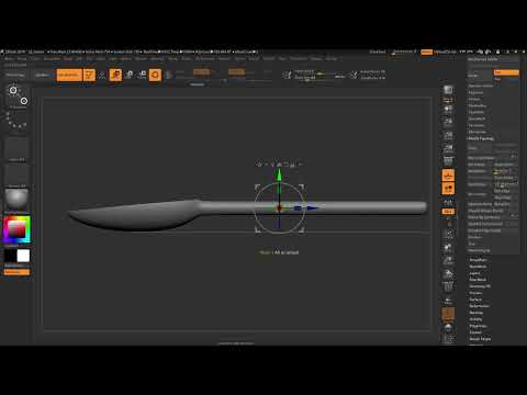
The video is only loaded from YouTube when you play it – data (including your IP address) is then transmitted to YouTube/Google. More in the privacy policy
The process is deliberately structured in a linear way. You start with an empty document and work your way step by step to the finished model. You can follow many of the intermediate steps directly, while others serve as inspiration for your own experiments. The timestamps in the screenshot placeholders help you quickly find the matching spot in the video.
Key Takeaways
- The screwdriver is made up of two main parts: the metal shaft and the handle. Both are modeled separately and combined later.
- The "Gizmo" deformer determines the rough shape before you cut out details.
- With ReMesh and Dynamic Subdivisions, you get a clean, even resolution, which is important for Booleans.
- Live Booleans with masking and Split Masked Points are the central tool for cutting out and notching.
- Mirror and Weld mirrors geometry, but requires the correct axis system.
- Array Mesh duplicates notches and details evenly around an axis.
- Using Polygroups and Group Split, you divide the model into material areas that you can later assign individually in KeyShot.
Step-by-Step Guide
Step 1: Creating the metal shaft as the base shape
Start with a new, empty document. A star object is suitable as a starting point because you can convert it directly into a Polymesh. To do this, activate Edit Mode and convert the object. Then you take the Gizmo and stretch the cylinder into a long, slender piece of metal. Make sure to define the proportions early, because they determine the overall look of the tool.

Step 2: Shaping the front rounding with a sphere
For the tapered front, you use a shape projection with a sphere. You place the sphere on the cylinder and stretch it to the desired length with the Gizmo. This method is often faster than modeling the rounding manually and delivers even transitions. You can still readjust the exact length of the tip later with Booleans.

Step 3: Rebuilding the mesh cleanly with ReMesh
After deforming, the topology is often irregular. Therefore, activate ReMesh and choose a suitable resolution, such as 60. You get a new mesh with predominantly quads and rectangles, which is very helpful for the later Booleans. Then you activate Dynamic Subdivisions and set the value to 4. This way you see a smooth rounding without permanently changing the mesh.

Step 4: Removing excess material with Live Booleans
Now you cut away the unnecessary areas. To do this, you create a cube over the mask, move it to the desired position, and activate Live Booleans. With the Split Masked Points command, you separate the object into its own Subtools. Then you can use the cube as a cutting tool and place the cut edge exactly where you need it. Since the cube has the same resolution as the main mesh, you don't need to set any additional subdivisions.

Step 5: Mirroring the model with Mirror and Weld
To create the underside, you use Mirror and Weld under Geometry, Modify Topology. Make sure the axis system is at the center of your model. To do this, hold down the Alt key, rotate the Gizmo, and move it to the center. Then select the appropriate axis, in this example the Y axis. The result is not perfect, but entirely sufficient for the exercise. For a clean cut on the sides, you repeat the process with the X axis.

Step 6: Refining the cut at the tip
Now create another cube that defines the lateral slope of the front part. Move it to the desired position with the Gizmo and subtract it. With a slight sideways movement, you get a more dynamic shape. If needed, you can align the edges straight by pulling them apart.

Step 7: Modeling the Handle as a Separate Subtool
Before you start the handle, save your project. ZBrush 2018 can occasionally crash during larger changes. Then add a new cylinder that will form the handle. Make sure the polygon count is sufficient, about 16 segments around the cylinder. Then move and deform the cylinder so that it sits well in the hand. Remember: the handle must have a similar resolution to the metal part so that the later Booleans work cleanly.

Step 8: Rounding Edges and Shaping Surfaces
At the end of the handle, you round the edges with the Bevel command. To do this, select an edge, press the space bar, and use Bevel with Loop Complete. For a finer final resolution, about four rows are enough. On the back, you then remove the Flat Island, close the resulting hole again, and select Convex so that the surface is curved outward. With Polygroups, you can also mark this surface as its own group.

Step 9: Creating Handle Grooves with Array Mesh
To make the handle easier to grip, you need grooves around the cylinder. To do this, create a normal cylinder, position it with the Gizmo, and cut it out of the handle with Live Booleans. With Array Mesh, you then duplicate this cylinder six times around the Z axis. Make sure to separate the Subtool cleanly beforehand with Split Masked Points, otherwise the rotation will not work as expected. You find the placement in the Y direction by trial and error. The values depend on your model; in this example, the value was about 1.6 to 1.8.

Step 10: Adding a Large Groove with a Curve
For an additional, larger groove in the middle of the handle, you work with a curve. Mark the affected area with Select Rectangle, holding Ctrl and Shift. Then you create a frame along the selection via Stroke, Curve, and Border. With the Curve Tube brush, a ring is created from it, which you adjust to the appropriate size with the Draw Size and the depth. When applying it, make sure that you separate the groups correctly and activate Dynamic Subdivisions on all components with the same resolution.

Step 11: Placing Lettering
For the lettering, you use the 3D Text and Vector Shapes plugin. Enter, for example, "ZBrush" and choose a thicker font so that the text can be cut out well. Set an extrusion, a bevel, and a sufficient resolution. Then position the text on the handle with the Gizmo in the front view. With the Subtraction mode, you cut it out of the handle and get a clean engraving.

Step 12: Tapering the Metal Shaft with a Taper Deformer
To make the front part narrower, you use the Taper Deformer. To do this, turn off the Polyframes and adjust the tapering. You can specify on which axes the effect should apply. When the result fits, you confirm with Accept.

Step 13: Preparing the Model for KeyShot
For the later materials, you divide the model into Polygroups. Select the metal area, use Slice or Group Split, and separate it from the remaining areas. This way, you get separate Subtools for polished metal, the handle, the lettering, and the cap. With Ctrl, Shift, and click, you can select areas specifically and turn them into a group with Ctrl and W. Make sure that each group is unambiguous so that you can assign it cleanly in KeyShot later.

Step 14: Converting the Booleans into a Tool and Exporting
Before you export the model, you convert the Live Booleans into real geometry. To do this, set the Subdivisions and select Make Boolean Mesh. You get a new Tool consisting of the individual Subtools. You can then send this Tool to KeyShot via the Ränderer button.

Step 15: Assigning Materials in KeyShot and Rendering
In KeyShot, you select the individual areas and assign suitable materials to them. For the metal shaft, a polished or galvanized metal is suitable, for the handle a hard plastic, for the lettering a light color, and for the back a black plastic. Then you adjust the lighting with an HDRI and set up the environment so that the screwdriver looks its best. With this preparation, the model is ready for your final render.

Summary – Modeling a ZBrush Screwdriver with Live Booleans and Array Mesh
You have seen how a complete tool is created from a simple cylinder. The path leads through basic shapes, remeshing, Live Booleans, mirroring, and Array Mesh up to the preparation for KeyShot. Especially important are the uniform resolution of all components and a clean group structure. With these fundamentals, you can build your own hard-surface objects step by step and adapt them to your vision.
FAQ
Which software do you need for this project?You need ZBrush, preferably version 2018 or newer, as well as KeyShot for the final render.
Is the screwdriver suitable for printing or production?No, the model serves exclusively as an exercise in modeling techniques. It is not a CAD model and is not intended for manufacturing.
Why does the model have to be split into Subtools before the Array Mesh?Array Mesh only works cleanly if the affected element exists as a separate Subtool. You separate it beforehand with Split Masked Points.
Why should all components have the same resolution?Equal resolutions ensure clean Booleans. Meshes of different density can lead to unsightly edges or errors.
What do you do if the Gizmo is in the wrong place?Hold down the Alt key and move the Gizmo to the center of the desired object using the corresponding icon.


