

Imagine you want to build a room that doesn't look like a collection of floating cubes, but like a real, well-thought-out structural component. This is exactly where the surround comes in. It logically connects two elements and creates a joint that immediately shows the viewer: Something has been built in here, someone has put thought into this.
The video is only loaded from YouTube when you play it – data (including your IP address) is then transmitted to YouTube/Google. More in the privacy policy
In the following, I'll show you how to build such a surround from a simple spline and the Extrude tool, align it cleanly, and make a shadow gap visible with SSAO. The technique is quickly learned, but the details determine whether the result is convincing. So take your time with the alignments and roundings.
Key Takeaways
The surround is a component with a function. Its job is to logically connect two elements. The shadow gap at the transition makes this connection readable in the image, regardless of whether screws are present.
Clean points are the foundation. In Points mode, set the spline's points to hard interpolation and align important points exactly using the values in the Structure Manager. Imprecise points lead to messy edges later on.
The rounding needs targeted segmentation. A maximum angle of about 14 to 15 degrees between segments delivers a smooth curve without overloading the object with unnecessary polygons.
SSAO shows the gap already in the viewport. With Gouraud shading and SSAO enabled, you can see the shadow gap during modeling and can directly assess the proportions.
An instance saves work. For the opposite side, you don't need a second extrusion. An instance that you mirror and position is enough, since the surround is axially symmetrical.
Step 1: Understanding the Outlook and Planning the Surround
Before you set the first point, you should know where the journey is heading. The surround will later be part of a wall that runs above a window and additionally has a ceiling molding and a baseboard. These individual segments will later be duplicated and assembled into a room. So plan the surround as a reusable module and not as a single object.

Step 2: Drawing the Spline
In the menu, select the Spline tool and activate the Spline Pen. Set the starting point at the desired location and draw the contour of the surround. For this back side, you can work a bit faster, since it will hardly be visible later. Just make sure the shape looks coherent overall.
Close the spline by clicking on the starting point. The resulting curved lines are still undesirable at this point because they create soft transitions that you don't need for the surround.

Step 3: Switching the Points to Hard Interpolation
Switch to Points mode and select all points of the spline. Then go via Mesh, Spline to hard interpolation. This turns the curve points into clear corner points. These corner points are the basis for further work, because only with them can the edges be aligned precisely.
Step 4: Aligning the Points Exactly
Not every point has to sit to the millimeter, but you should definitely place some points exactly above one another. In the example, this concerns two points that should lie on the same horizontal line. To do this, open the Structure Manager and select the two points. They appear there with a dark highlight.
Set the X value for both points to the same amount. The easiest method is to drag the value of the slightly larger point to that of the smaller one. In the same way, you align points of equal height by matching the Y values. Hold down the Shift key if you want to select several points at the same time.
You don't have to round all points. Concentrate on the areas that will be visible later. The back side and parts that no viewer sees can remain rougher. This saves time without reducing the quality of the visible result.

Step 5: Rounding the Corners with the Radius
Now it's time for the rounding. In the Object Manager, go to the Mesh Spline section and set the radius to a value of about 1.8 cm. This value has proven itself. The default setting is often significantly higher, which leads to excessively wide roundings.
You can adjust the angle for the segmentation of the rounding via the Phong setting. By reducing it to a smaller value, you get more intermediate steps. However, keep an eye on the value, because too many segments bring no visible benefit. For finer adjustments, the Alt key is useful, as it allows input in tenth-of-a-degree steps.

Step 6: Extrude the Spline Object
Now switch to the Object Manager and create an object from the spline. Use the Extrude tool for this. By default, Cinema 4D extrudes the spline in the Z direction. You don't need to change this in this case, since the direction matches the position of the frame. You can adjust the direction at any time if your setup requires it.

Step 7: Check and Optimize the Segmentation
Switch the view to the line display. There you can see how densely the rounded areas are subdivided. You will probably find that the number of segments is too high. This is because the spline angle was chosen too small.
Therefore, open the settings of the spline object and increase the maximum angle. A value between about 14 and 15 degrees delivers a rounding with six polygons that matches the original in quality. Straight surfaces need no intermediate points, but the rounded areas do. Make sure that the rounded areas turn out evenly on both sides.

Step 8: Adjust Caps and Roundings
In the Extrude object you will find options for the caps and roundings. Activate them so that the edges at the ends are cleanly finished. Set the thickness of the caps to about 1 cm and the end step to about 0.8 cm. For the segments of the rounding at the ends, five subdivisions are usually enough.
Repeat these settings on the back and on the underside. This way, the frame looks consistent from all relevant sides. Check the result in several views before you continue.

Step 9: Define the Width of the Frame
The frame now looks a bit too wide. Open the settings of the Extrude object again and reduce the width to about 12 cm. In most cases, this value suits a wall thickness and a classic proportion. Adjust it later to the overall design of your room.

Step 10: Position the Frame
The frame must not simply stand in the middle of the room. It must connect exactly to the cube. Therefore, move it backward and forward until it sits in the right place. What is decisive is that the frame rests against the cube and a connection is created there.
The connection does not have to be accurate to the millimeter. What matters is that contact occurs between the frame and the cube, from which a shadow gap later emerges. Whether screws are present or the element is merely plugged in makes no difference to the look. The gap itself is the actual design feature.

Step 11: Duplicate the Frame for the Opposite Side
For the upper end of the cube you need the same frame. Instead of extruding again, you create an instance of the existing object. Move the instance to the upper position. At first it appears mirrored, but since the frame is axially symmetrical, this does not matter. You can attach it from the left or the right.
Move the instance so close to the edge that it cleanly encloses the cube. Here, too, an approximate alignment is sufficient, as long as the contact is clearly visible.

Step 12: Make the Shadow Gap Visible with SSAO
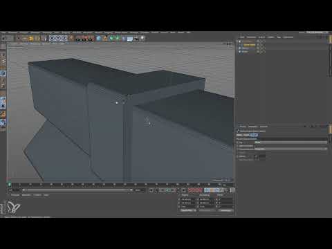
Switch the display to Gouraud Shading. This makes the lines disappear, and you see the object as a closed surface. Then open the viewport options and activate SSAO (Screen Space Ambient Occlusion). This function has been available since Cinema 4D R18.
After activation, a soft shadow immediately appears at the transitions. This very shadow gap makes the frame recognizable as a functional element. It is convincing even in the viewport, long before you work with materials and light. At this point, check whether the gap appears at all desired edges, and correct the position if necessary.

Summary ??? Modeling a Frame in Cinema 4D: Shadow Gap with SSAO
You have now seen how to create a frame from a simple spline that works convincingly as a component. You set the points to hard interpolation, aligned them precisely, and rounded them with a suitable radius. With the Extrude tool, you turned it into an object and controlled the segmentation via the angle. Afterwards, you adjusted the caps, width, and position, mirrored the frame using an instance, and made the shadow gap visible with SSAO. You can now duplicate this module as often as you like to build a complete room step by step.
FAQ
Why should I switch the points to hard interpolation?Hard interpolation turns the soft curve points into clear corners. Only then can the edges be aligned precisely and later rounded cleanly.
Do I have to align all points of the spline exactly?No. Focus on the points that will be visible later. Back sides and hidden areas can remain rougher.
Which angle value is suitable for the segmentation of the rounding?A maximum angle of about 14 to 15 degrees delivers a smooth rounding with six polygons. Smaller values create unnecessarily many segments.
Why don't I see a shadow gap after activating SSAO?Check whether you have switched the display to Gouraud Shading and whether the frame actually touches the cube. Without contact, no gap is created.
Do I need screws for the frame to look believable?No. Whether screws are present or the element is simply plugged in makes no difference to the look. What matters is the visible connection and the resulting shadow gap.
Can I copy the frame for the opposite side?Yes. An instance saves work, since you don't have to extrude again. Because the frame is axially symmetrical, you can use it mirrored without any disadvantages.

