

A space station only looks believable when the small details are right too. A connecting element that is recessed into the ceiling is one such detail. It exists only once in the model and should therefore be axially symmetrical. In this tutorial you follow the build in Cinema 4D: from tidying up the scene and drawing a spline to the finished extrusion body that fits cleanly into the existing ceiling construction. The decisive trick is to align the spline's points exactly via the Structure Manager before you extrude them.
The video is only loaded from YouTube when you play it – data (including your IP address) is then transmitted to YouTube/Google. More in the privacy policy
Key Takeaways
- You should remove objects you don't need, such as the large floor plane, early on so the scene stays clear and manageable.
- Group related objects in a null object that you can show and hide with one click.
- The Symmetry object mirrors the geometry, but it does not replace the clean alignment of the spline points.
- In the Structure Manager you match the values of opposite points: same Y value, same X value with the opposite sign.
- With hard interpolation all points become corner points, so the spline keeps sharp edges.
- After extruding in the Z direction, you position the object precisely on the ceiling with the Move tool.
Step-by-Step Guide
Step 1: Tidy up the scene
Start by tidying up. In the initial state you see the classic floor, which is only displayed up to a certain limit. It would extend to the horizon and is not needed for this detail. So simply delete it. You can also ignore open gaps at the back edge, since they play no role in working on this element.

Step 2: Align the view to the ceiling gap
You want to close the gap in the ceiling. For that it is enough to leave only the two front ceiling segments visible. In the side view you can then clearly see the area between the ceiling segments and the underswing. This is exactly where the connecting element should sit. A simple cube would quickly provide a solution here, but for a more design-demanding detail a freely drawn spline is worthwhile.

Step 3: Group the scene in a null object
Place all previous objects in a new null object and name it, for example, "Scene". This way you can hide the entire environment with one click as soon as you want to concentrate only on the corners. This is especially helpful when you switch back and forth between different views to quickly get to the desired points.

Step 4: Set colors for orientation
Set the null object "Scene" to red so it is clearly recognizable in the view and you don't lose your bearings. You mark the first Symmetry object with green. Since the element exists only once, it is not a problem that two objects stand one behind the other. You work in the front view, where the two objects do not interfere with each other.

Step 5: Draw the spline with the world grid
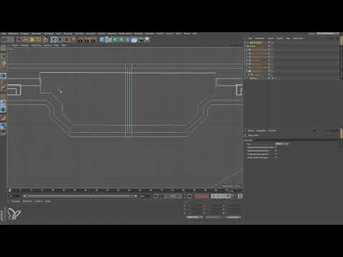
Activate the world grid. It helps you place points at even positions, which makes symmetry easier later. Begin at the top of the ceiling with a first point and then follow the shape of the underswing. This shape shows a functionality that gives the element a logical purpose. Place the points at roughly equal grid positions until you have made the transition back up. A few inaccuracies are normal at this point, because they will be corrected in the next step.

Step 6: Check points in the Structure Manager
Now select only the spline. As long as several objects are selected, the Structure Manager shows nothing. Then open the Structure Manager to see all the points of the spline with their coordinates. This is where it is decided whether your element will be symmetrical later. It is best to first select a point at the top in order to use its values as a reference.
Step 7: Match opposite points
For a symmetrical result, you need two rules. Opposite points need the same Y value. In addition, they need the same X value, but with the opposite sign. So if a point has the X value 167, the opposite point gets -167. In the video, this value is visibly corrected by removing the minus sign. Proceed pair by pair and compare the values in the Structure Manager before you continue.

Step 8: Define corner points with hard interpolation
The point at the top end should be a corner point, and this applies to all points so that the shape is not rounded later. Therefore, select all points and choose hard interpolation for the spline. This way you can be sure that all points are actually corner points. This setting is especially important if the element is meant to look like a component with clear edges.

Step 9: Check and correct the remaining points
Now go through the remaining points. Select a point, note its X value, and enter the same amount with the reversed sign for the opposite point. The lower point should usually already fit, so you only need to move it up to align the two sides in parallel. Pay particular attention to deviations in the X values. If they are too large, the point lies far outside the desired shape. In this case, enter the correct value directly and check the result by double-clicking the field. You don't need to rush, because a careful approach pays off when it comes to symmetry.
Step 10: Extrude the spline and align it precisely
Switch back to the perspective view and to the Object Manager. Place the spline into an Extrude tool. The body is extruded correctly in the Z direction. However, it doesn't fit exactly in place yet, so you have to readjust the object with the Move tool. Check the position until the element at the top merges exactly into the ceiling.


Step 11: Finalize the position and fine-tune
Finally, move the element to the exactly right position in the Z direction so that it ends precisely at the desired edge. Then decide whether the element should stay in this position or whether you would like to have it somewhere else. If you also need a copy on the back, you can place it accordingly. Optionally, you can round the edges slightly, just as you have already done with the other components. If you then show the entire scene again, the ceiling looks almost finished, so that one could take it for a real space station ceiling.

Summary – Cinema 4D: Modeling a symmetrical connecting element for a space station
You have seen how an axially symmetrical connecting element for the ceiling of a space station is created. The process begins with tidying up the scene and bundling the objects in a null object. Then you draw the spline on the world grid and align its points in the Structure Manager. Opposite points receive the same Y value and the same X value with the reversed sign. With hard interpolation, you ensure sharp corner points. Only after that do you extrude the spline in the Z direction and fit the element exactly into the ceiling with the Move tool.
FAQ
Why do I have to select only the spline before I open the Structure Manager?As long as several objects are selected, the Structure Manager does not display any points, so you cannot edit the coordinates.
How can I tell whether my spline is symmetrical?Compare opposite points in the Structure Manager. Identical Y values and identical X values with opposite signs indicate a symmetrical shape.
What is hard interpolation used for?It ensures that all points of the spline become corner points. As a result, the edges of the connecting element stay sharp and are not rounded.
Why do I put the scene into a null object?The null object bundles all objects into a group. This way you can show or hide the environment with one click and concentrate on the details.
Do I have to create the element on the back again?Since the element appears only once in the ceiling, one copy is enough. A second position is only needed if your design explicitly calls for it.

