

A headlight housing rarely consists of a single part. Usually it needs a back wall, a matching front section, and a connecting tube that holds everything together light-tight. In this tutorial, you build exactly this interplay in Cinema 4D: You extrude the back wall, mirror it via a Symmetry object to create the front section, and then generate the tube from the spline. Along the way, you also learn what to watch out for when shrinking polygons.
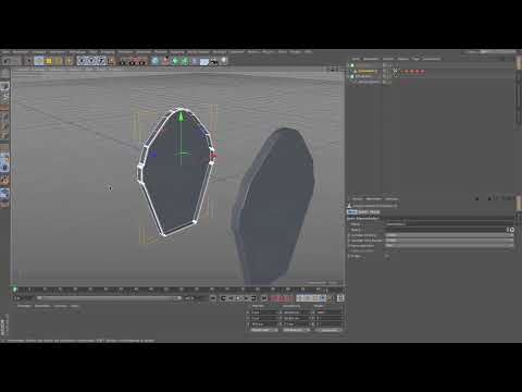
The video is only loaded from YouTube when you play it – data (including your IP address) is then transmitted to YouTube/Google. More in the privacy policy
Key Takeaways
- The spline is kept as the starting basis. Duplicate it before you process it further, and hide the original.
- With the Extrude tool and the Inner Extrude (key I), you shape the curves and cover surfaces of the back wall.
- Don't overdo the Inner Extrude. Shrinking too much produces black, faulty polygons.
- The Symmetry object mirrors the back part automatically. The mirror plane must be aligned correctly, otherwise you will only see one part.
- The tube is created from a copy of the spline. Adjust its size with the Scale tool so that there is room for cooling fins in the housing.
Step 1: Secure the spline and hide the original
Before you get started, you should protect the spline. It is your starting basis for all further parts, and you want to be able to use it again at any time if something goes wrong. So copy it with Command C and Command V. You continue working with the copy, and you hide the original via the traffic light switch in the Object Manager until the dot lights up red. You will do the same for the renderer later. The copy is thus your playground, and you can experiment without endangering the original.

Step 2: Extrude the back wall and connect it into one object
Now you take the copy of the spline and apply the Extrude tool. This creates a three-dimensional body from the spline shape. With the C key, you convert the result into an editable object. Then the curve and the cover surface of the back wall become visible. The lower and upper halves are initially still separate objects. Hold down the Shift key and click on both one after the other. Then you connect them using the Connect Objects command and delete the superfluous remnants, so that only a single part remains.

Step 3: Inner Extrude for the half-shell shape
Now the rather voluminous part should look like a half shell. To do this, switch to Polygon editing mode and activate the Live Selection tool. Select the entire surface. At first glance, the part looks like it consists of only a few surfaces, but internally Cinema 4D manages the surface as many small polygons that are treated as one connected N-gon. That is why the surface can be selected as a whole.
Now press the I key for the Inner Extrude. You can also find this tool in the menu under Create Mesh, where the shortcut I is displayed as well. Pull the surface inward until the wall becomes thinner and the shape is reminiscent of a shell.

Step 4: Observe the limits of the Inner Extrude
When shrinking, pay close attention to the geometry. If you go too far, black polygons appear in certain places. They are faulty because they are not cleanly defined mathematically and could never look like that in reality. You don't want to see such surfaces in the finished model. So only pull the extrusion until the curve and the inner extrusion are roughly the same size. That is enough for a clean shape.
Keep in mind: You are not constructing a technical component to CAD specifications here. The headlight will never be manufactured to these dimensions. The goal is a look that is as perfect, realistic and appealing as possible, not an exact construction.

Step 5: Move inward to make room for the tube
Next, press the D key and move the surface inward. The tube that you insert later should be sunk into it. To make sure the selection doesn't remain unintentionally, first click briefly into the viewport with the Move tool. This deselects the selection. You don't need to build a second copy of the back wall. The Symmetry object takes care of that in the next step.

Step 6: Mirror the front with the Symmetry object
So that you don't have to build twice, place your back part in a Symmetry object. To do this, put the object into the Symmetry object in the Object Manager. At first you only see a single part. This is because the Symmetry object first has to be aligned. Click on it and check the mirror plane. If it is positioned so that the object mirrors onto itself, nothing visible happens. You need the XY plane. Select it, and the mirrored front will appear.
Both parts are now about 33 centimeters apart. Caution: If you now drag the object, you move both halves at the same time, because the Symmetry object is still active. Therefore, click on the actual object, switch to Object editing mode and pull it apart. Half of the distance is 16.5 centimeters. You enter this value in the Coordinates Manager in the axis that is perpendicular to the mirror plane. With the XY plane, this is the Z axis. Confirm the entry, and you will have exactly the desired distance.

Step 7: Extrude the tube from the spline
The tube connects the front and back parts and ensures that the housing is light-tight all around. It also comes from the spline. The spline is not visible at the moment, but you surely saved it earlier. Copy it again with Command C and Command V and get an Extrude object. Place the spline copy inside it.
The tube will initially protrude somewhat beyond the target. Then pull it back with the Move tool until the white line on the top and bottom lies exactly inside the shell. If you want to check the fit precisely, switch to a side view. There you can see very clearly how the edges converge. You may need to lengthen the tube so that it is anchored cleanly in both halves. In the end, it should fit tightly on all sides.

Step 8: Fit the tube by scaling
Now a problem appears: The tube is still too large. Later, cooling fins are supposed to sit between the shells in the housing. However, they would need space that the tube would completely fill. So you have to make the tube considerably smaller. The easiest way to do this is via the spline: Click on it, select the Scale tool and shrink the shape in the viewport. The distance to the edge should be about one centimeter.
Look at the result from several sides. At the top and bottom it fits, but in the Z direction you may have made the tube a bit too small. You can usually see this better in a frontal view. If the gap is even on all sides and the tube still sits cleanly in both shells, you can leave the setting as it is.

Step 9: Better assess shadows with SSAO
Finally, a tip that makes checking easier. Use a current Cinema 4D version and activate SSAO, i.e. Screen Space Ambient Occlusion, in the view options. This function calculates soft shadows in recesses and joints directly in the viewport. Turn it off and on again once to see the difference. With the option activated, you can recognize shadow gaps and transitions much better, and you can already see in the viewport what the housing will look like after rendering.

Summary – Spotlight housing in Cinema 4D: Building the back panel, front and tube
You have now built the basic framework of a spotlight housing. The starting point was the spline, which you saved and reused in a targeted way. From it, the back panel was created through extrusion and inner extrusion. A Symmetry object produced the front, which you positioned at a distance of 33 centimeters. The tube was also created from a spline copy and was reduced in size by scaling so that it leaves room for later cooling fins. When shrinking, always watch out for faulty polygons and use SSAO to check the results early.
FAQ
Why should I copy the spline before editing?The spline is your starting basis for the back panel and the tube. With a copy, you can experiment without changing the original, and you can fall back on it at any time.
Why do I only see one part after inserting it into the Symmetry object?The Symmetry object must first be aligned correctly. Select the XY plane as the mirror plane, otherwise the object mirrors onto itself and the front remains invisible.
What do the black polygons after the inner extrusion mean?They occur when you push the inner extrusion too far. These surfaces are mathematically faulty and should be avoided. Reduce the extrusion until the rounding and the inner extrusion are approximately the same size.
How do I calculate the distance between the front and back parts?With a total distance of 33 centimeters, you move each half by 16.5 centimeters. You enter this value in the Coordinates Manager.
Why does the tube have to be made smaller?Cooling fins are supposed to sit between the shells later. A tube that is too large would completely fill this space, so you shrink the spline until about one centimeter of clearance remains.
What does the SSAO option do?SSAO calculates soft shadows in joints and recesses directly in the viewport. This way you can recognize shadow transitions and fits even before rendering.

