

A heavy spotlight needs a mount that doesn't shift under every load. This is exactly what you will develop in this tutorial: a rotating mechanism with a carriage, a joint bracket, and a locking disc. You will work exclusively with basic objects in Cinema 4D: cylinder, cube, and disc, supplemented by instance, grouping, and symmetry. A detail photo of the mechanism serves as a reference, and you don't need any experience with manual modeling to follow the steps.
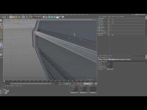
The video is only loaded from YouTube when you play it – data (including your IP address) is then transmitted to YouTube/Google. More in the privacy policy
The focus is on understanding the structure. If you know which parts move how and where they sit, the dimensions and positioning become much easier.
Key Takeaways
The mechanism consists of three main parts: two cylinders as a guide, a cube as a joint bracket, and a disc as a lock. All three elements together form the carriage that can be moved along the truss.
An instance instead of a copy saves polygons and keeps both sides in sync. If you change the original cylinder shape, the instance adjusts automatically.
With the axis lock, you move objects precisely in only one direction. This prevents unwanted shifts when placing small parts.
A disc becomes a true volume via the Cap option. Without the cap enabled, the object remains an empty shell.
Grouping and mirroring using the Symmetry object doubles the mechanism with little effort.
Step-by-Step Guide
Understanding the Function of the Mount
Before you create any object, you should know what the construction is built for. The spotlight hangs on a yoke, and this yoke can be moved along a fixture via a carriage. This way you can realign the center of gravity depending on the lens. Your task is to recreate exactly this carriage before you model the yoke itself.

Analyzing the Detail Photo and Side View
Open the detail photo or switch to the side view. There you can see that at the rear end of the carriage sits a brake disc, which locks the yoke in place via a screw. Make a note of the arrangement: two cylinders guide the movement, a cube forms the joint bracket, and the disc lies behind it. This order will later determine your working steps.

Creating the First Cylinder
Get a cylinder basic object from the menu. By default, the cylinder is aligned to the Y axis and is built in the Z direction. First set the radius to about 0.5 cm. This is a guideline value that you will check against the model later.

Adjusting Radius and Height
First set the height of the cylinder roughly to 200 cm so that you can see the object well. Then move it to the position in the spotlight housing. It becomes apparent that 0.5 cm looks too thick. Reduce the radius to 0.4 cm. This value looks much more realistic and fits the opening better.

Setting the Length Precisely
Shorten the height until the cylinder fits exactly into the corner at the top of the housing. The speaker first finds 39 cm too long and finally chooses 36 cm. Remember this value, because later it also determines the number of segments per part.

Positioning the Cylinder with the Axis Lock
When you use the Move tool, you can easily move the object in unwanted directions as well. Therefore, turn off the X and Z axes so that only the Y axis remains active. With this restriction, you push the cylinder cleanly upward. For a sideways correction, turn off the Y axis and turn the X axis back on. If the movement is jerky, move a bit farther away from the object, and the viewport usually responds more precisely again.

Creating an instance for the second side
Instead of creating a second cylinder with the same values, you drag an instance of the first cylinder to the lower position. If you later change the diameter of the original, the instance automatically grows with it. This saves you work and avoids discrepancies between the parts. You also remove the caps of the cylinder if you do not need them. This significantly reduces the polygon count, because with 36 segments, 72 polygons are eliminated.

Using the cube as a joint bracket
The cube takes on the role of the joint bracket. Set its edge length to 2 cm, because at this size it quickly leads to a usable result. Move it into the free area between the cylinders. Make sure that enough distance to the housing wall remains. If necessary, move the two cylinders slightly outward.

Adjusting the cube to the cylinders
Increase the height of the cube so that it encompasses both cylinders. Move it closer together in the process and use the photograph as a guide. This step is done by eye and does not have to be exact. Just make sure that the proportions match the photo.

Rounding the edges of the cube
Open the object properties of the cube and select the Fillet option. The radius should be about 0.2 cm. The value looks soft and matches the original. After rounding, the joint bracket looks much more realistic.

Grouping and mirroring the slide
You need the mechanism on both sides of the headlight. Therefore, select the cylinder, instance and cube and group them with Alt+G. Rename the group to Slide. Then you create a Symmetry object and drag the slide beneath it. This mirrors the mechanism to the other side. Afterwards, check whether the slide can move the same way on both sides.

Creating the brake disc as a disc
For the locking disc, you use a parametric Disc primitive. First align it to the X-axis, since it also appears to be incorrectly oriented. The inner radius stays at zero, because you are not building a washer. Set the outer radius to 4 cm. With this value, the disc roughly hits the right size.

Setting the segmentation for the proportions
Increase the segmentation to 5 so that you can control the proportions better. Then convert the disc into a polygon object with the C key. The Live Selection tool lets you select the inner polygons. Move these inward, and you get the typical shape of a brake disc with a recess.

Thickening the disc by extruding
After this step, the disc is still flat. Select all polygons and open the Extrude window with the D key. Here you set a thickness of 0.15 cm. It is important that the Caps option is enabled. Without it, the disc remains an empty shell and has no filling on the back. Confirm with Apply.

Naming and positioning the brake disc
Name the object Brake Disc, even though the speaker basically refers to it as a locking disc. Place it at the spot where the screw fixes the bracket. You can add spacer rings and washers as further elements. At the end, check the overall view so that the mechanism looks coherent.

Summary ??? Modeling a Cinema 4D Locking Disc: Step-by-Step Guide
In this tutorial, you have rebuilt a complete rotating mechanism. Two cylinders with an instance guide the slider, a rounded cube serves as the joint holder, and the extruded disc takes over the locking function. The axis lock, the instance, and the Symmetry object saved you a lot of work. If you check the dimensions step by step, you will get a model that comes very close to the original.
FAQ
What is the purpose of the instance instead of a second cylinder?The instance automatically adopts all changes made to the original and saves polygons, because you only have to remove the caps once.
Why should I use the axis lock?The axis lock prevents unwanted shifts in other directions and makes it easier to place small objects precisely.
What radii and heights are recommended for the cylinder?The radius is 0.4 cm and the height is 36 cm, although the values should be checked against the model.
Why does the cap have to be enabled for the disc?Without an enabled cap, only an empty shell is created, whereas with it a complete body with volume is created.
How do I mirror the slider to the other side?Group the parts with Alt+G, name the group, and then create a Symmetry object, under which you drag the slider.

