

The grip screw is one of the components that give a spotlight its typical character: round, smooth, and with seven small fingers along the edge. Precisely because it looks so organic, it can be built easily from a simple cylinder. You only need a few tools, but a bit of patience when shaping the curvature and distributing the edges. In this tutorial, I guide you step by step from the reference view to the finished, inserted screw.
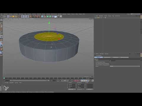
The video is only loaded from YouTube when you play it – data (including your IP address) is then transmitted to YouTube/Google. More in the privacy policy
Key Takeaways
A cylinder with sensibly chosen segments is the foundation for the entire shape. The number 21 results from seven fingers with three edges each. You create the curvature by hand before letting the SDS object take care of the smoothing. A loop cut helps for a sharper edge at the rim, and you scale the finger edges only in X and Z so that the height is preserved. It is best to create the model in a separate scene and copy it into the spotlight only at the end.
Preparation: Reference and Working Scene
Before you get started, open the side view of the spotlight in the Picture Manager. In a side view, you can clearly see how strongly curved the grip screw is and how much space it takes up. Enlarge the image to about one hundred percent, and you will see the round shapes much more clearly.

Do not model the object directly in the spotlight scene. Other objects are already located at the origin of the coordinate system there, and otherwise you would have to laboriously move every new part. Instead, create an empty scene via "File New". Everything you build there, you simply copy into the spotlight later.

Creating the Base Cylinder
Create a cylinder as the base. Initially set it upright, because you can tilt it at any time later. The radius should be approximately 2.8 cm. You do not need to determine the height exactly, because you will correct it anyway when adjusting to the reference. Make sure your cylinder sits completely at the origin so that you can work cleanly later.

So that you do not have to constantly navigate while modeling, select the object and press the O key. The view then jumps directly to the object, and you can view it comfortably.

Planning the Segmentation
Now you define the structure. The grip screw has seven fingers, and each finger should lie between two gaps. For each finger you therefore need three edges: two for the gap and one for the finger itself. That gives seven times three, so 21 segments around the circumference. This number is divisible by seven, which is why it fits the shape perfectly.
Four height segments are enough for the curvature on the top surface. You do not need more there, because the curvature will be smoothed out later anyway.

Then convert the cylinder into a regular polygon object. Only then can you edit individual faces and edges.

Shaping the Curvature on the Top
Switch to Polygon mode and, using the Live Selection, first select all polygons on the top except for the outer ring. Then move this selection upward. Hold down the Ctrl key while selecting if you want to deselect faces again.
Then view the object from the side and pull the rings further upward step by step. Let the transition toward the center flatten out gradually so that no hard kink occurs. A gentle angle at this point will later ensure an elegant shape. Repeat the process for the center until the desired curvature is reached.

The curvature could also have been created with an oil tank object. However, I recommend hand modeling, because you can adjust the shape exactly to your taste and the polygons will be needed later anyway.

Selecting the finger edges
Now switch to edge mode. Before you continue, you should optimize the object via the command menu. This way you avoid problems with duplicate points or faulty edges later on.
Now you select every third edge around the circumference, because that is where the fingers will be created later. You start at one spot, leave two edges unselected each time and select the third. That sounds simple, but it requires concentration. Keep counting consistently while selecting and check at the end whether the pattern repeats all the way around. If you lose count, it is better to correct it immediately rather than fixing it later.

Scaling the fingers outward
The selected edges should protrude outward. For this you can simply scale the edges. This is much faster than moving each edge individually. Select the Scale tool and deactivate scaling on the Y axis. The height should remain unchanged; you only change the width in X and Z.
Then drag outward from the center. The fingers protrude evenly, and the gaps between them remain nicely rounded. If the shape looks too tall to you later, you can still slightly reduce the Y axis. In this example, however, the shape already fits, so you can leave it as it is.

Using the SDS object for the rounding
Now the SDS may take over the smoothing. First deselect all edges so that nothing is selected anymore. Hold down the Alt key and click the SDS icon to place it above the cylinder. The shape immediately becomes soft and round.
At first glance this looks good, but the edges at the top and bottom are both equally soft. The grip screw, however, has a gentle curvature at the top and a clearly sharper edge at the bottom. That is exactly what we will work on in the next step.

Setting a sharper edge with the Loop Cut
Click the cylinder and choose the Loop Cut in the Create Mesh menu. Place the cut close to the bottom edge. In the editor you can precisely adjust the distance via the slider or the input field. Finish the process with Escape or by choosing another tool, then the cut will be applied.
If you now activate the SDS object again, you will see that the edge at the border turns out much sharper. That is exactly the effect the real grip screw has.

Adjusting the subdivision of the SDS
The editor displays the surface at subdivision level 2. This setting is very fine for the editor view, but it is calculated even finer when rendering. For such a small detail, level 1 is often enough in the editor. The model is then not quite as smooth anymore, but it noticeably saves computing time.
You achieve the final quality when rendering with the higher level. So if you set level 1 in the editor, you save polygons and thus render time, without sacrificing the result.

Extruding the screw in the center area
The grip screw is actually a screw, after all, and it needs a way for it to be tightened. To do this, select the 21 polygons in the middle of the top side that form the center area. Then you extrude them with the D key. The extrusion gives the part the necessary height and makes it look like a real screw cap.
At the end, give the object a meaningful name, for example "Griffschraube". This makes it easier for you to keep an overview later, when the headlight consists of many parts.

Transferring the Handle Screw into the Headlight
Copy the finished object via the Edit menu. Then switch to your headlight scene via the window menu and paste it there via Edit and Paste. The object lands at the origin again, and you can now freely move and rotate it.

Positioning the Handle Screw
Drag the screw to the right place. To do this, you need to rotate it by 90 degrees so that it sits across the headlight. Then move it upward and sideways until it stands exactly where it is supposed to work later. The screw must meet a counter thread on the opposite side so that it can clamp the bracket in place.
When positioning, pay attention to the holes in the headlight. They may not immediately match the new position. You can simply move the holes upward by feel until they look right again. An exact measurement is not strictly necessary for this.

The Lock Nut as a Simple Addition
If you like, you can also model a lock nut as a counterpart. A cube with an edge length of about 2 cm is enough for this. Push it outward until it fits the right spot on the bracket. The part is not particularly complicated, but it illustrates very well how the bracket is locked in place later.

Understanding How It Works
The locking disc on the bracket is only a few millimeters thick. On it there is a thread that attaches directly to the brake disc. When you screw the screw in, a piece of sheet metal presses on the disc, and the entire bracket is fixed. This mechanism is not easy to recognize in the original, but with the model you get a rough idea of it.

The Final Finishing Touches: Highlights and Rounding
Finally, it is worth taking a look at the highlights. If you make the model slightly narrower and add small roundings to the edges, the light will reflect more nicely later. A rounding with a value of about 0.05 is enough for the small edges on this screw. Test the effect in the render before you settle on the value.

Summary ??? Modeling a Handle Screw in Cinema 4D: Step by Step
The handle screw is created from a cylinder with 21 segments, whose curvature you shape by hand. The fingers are created by scaling every third edge, while the SDS takes care of the smoothing. A loop cut sharpens the lower edge, and an extrusion turns the part into a real screw. Model in a separate scene and only transfer the finished object into the headlight at the end. This way you keep an overview and save time later when rendering.

FAQ
Question: Why are 21 segments used?Answer: The number 21 is divisible by seven, so each of the seven fingers gets three edges: two for the gap and one for the finger.
Question: Do I have to measure the height of the cylinder exactly?Answer: No, you can correct the height at any time when adjusting to the reference. What matters most is the radius of about 2.8 cm.
Question: Why do I deactivate the Y axis when scaling?Answer: This way the height of the handle screw is preserved, and only the fingers are pulled outward in X and Z.
Question: What is the loop cut for?Answer: It adds an extra edge close to the border, which makes the lower edge look sharper than the soft top.
Question: Which subdivision level should I choose in the editor?Answer: For modeling, level 1 is usually enough, as it requires fewer polygons. The higher level 2 only takes effect when rendering and then provides finer smoothing.
Question: Why should I model in a separate scene?Answer: In the headlight scene, objects already sit at the origin, which makes moving new parts cumbersome. In an empty scene, you work in a more organized way.

